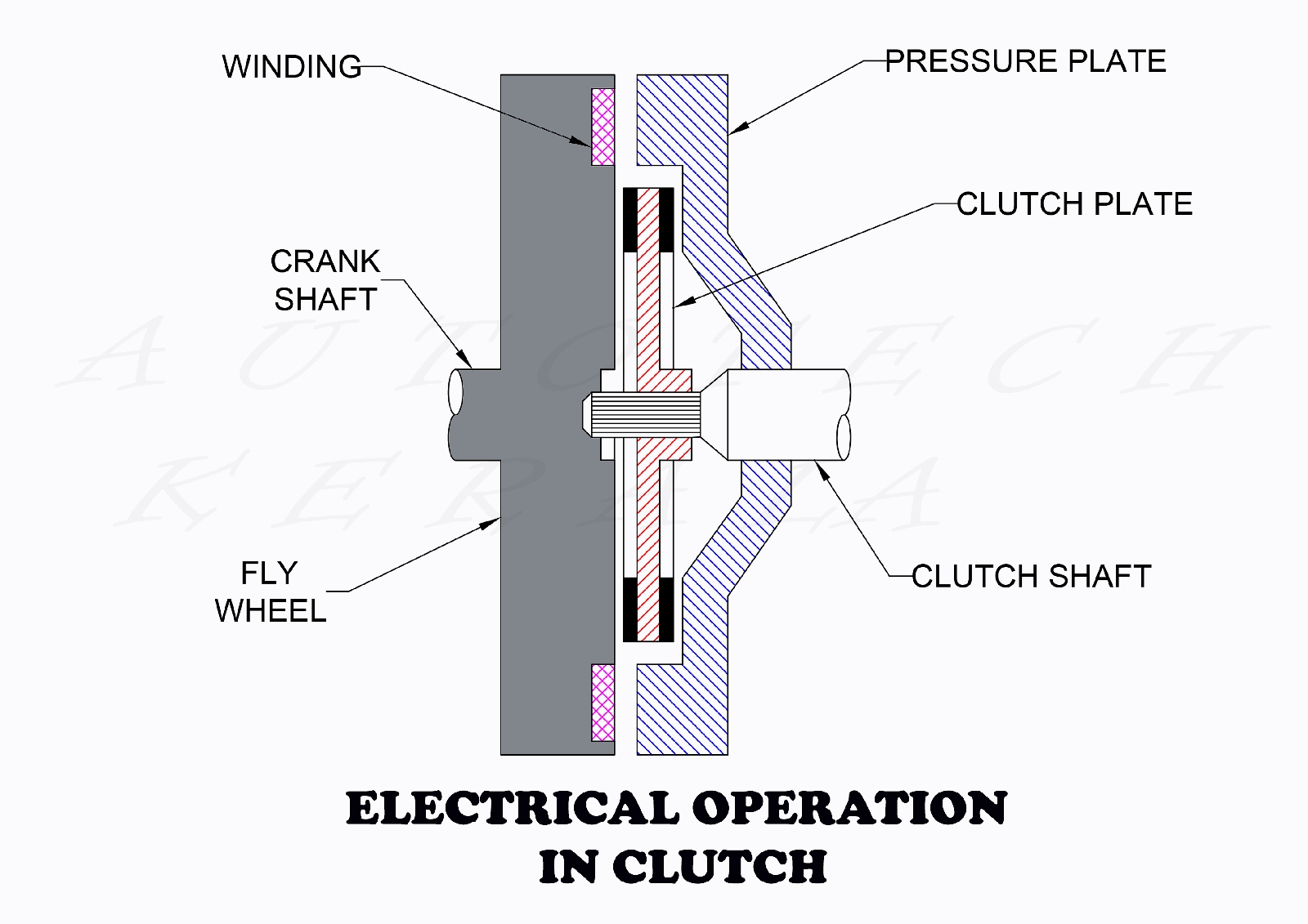
ELECTRICAL OPERATION IN CLUTCH ( MAGNETIC CLUTCH)


MAIN PARTS

1. FLYWHEEL
2. WINDING
3. CLUTCH PALTE
4. PRESSURE PLATE

CONSTRUCTION

In this type of clutch operation, a winding is provided on flywheel. Also the clutch plate is placed in between flywheel and pressure plate. The winding is connected a switch in the gear lever through engine dinamo. The switch is always in closed condition.

WORKING


 In electro magnetic clutch, the winding on the fly wheel produces a electro magnetic filed. It attracts the pressure plate towards the flywheel. When the engine rpm increases, more current flows through the circuit. It helps the winding to produce more electromagnetic flex. When the driver changes the gear, the switch on the gear lever become open condition. It causes to cut off the circuit in the winding on flywheel. So the magnetic filed in the winding is removed. It causes to make a gap between clutch plate and fly wheel. So the power from the engine can't be transmit at this time.


ഇലക്ട്രിക്കൽ ഓപ്പറേഷൻ

പ്രധാന ഭാഗങ്ങൾ

1. ക്ലച്ച് പ്ലേറ്റ്
2. ഫ്ലൈ വീൽ
3. വൈൻഡിംഗ്
4. പ്രഷർ പ്ലേറ്റ്
5. ക്ലച്ച് ഷാഫ്റ്റ്

നിർമാണം

സിംഗിൾ പ്ലേറ്റ് ക്ലച്ചുകളെപ്പോലെ തന്നെയാണ് ഇലക്ട്രോമാഗ്നറ്റ് ക്ലച്ചുകളുടെ നിർമ്മാണം. ഇതിൽ പ്രഷർ പ്ലേറ്റിനെ ഫ്ളെവീലിലേക്ക് ചേർത്ത് നിർത്തുവാൻ ആവശ്യമായ ബലം നൽകുന്നത് ഫ്ലൈ വീലിൽ നൽകിയിരിക്കുന്ന ഒരു വൈൻഡിങ്ങ് പുറപ്പെടുവിക്കുന്ന കാന്തിക ബലമാണ്. എല്ലാ ക്ലച്ചുകളിലെയും പോലെ തന്നെ ഫ്ലൈ വീലിനും പ്രഷർ പ്ലേറ്റിനും ഇടയിലാണ് ക്ലച്ച് പ്ലേറ്റ് സ്ഥാപിച്ചിട്ടുള്ളത്. എൻജിൻ ഡെനോമയിൽ നിന്നും ലഭിക്കുന്ന വൈദ്യുതോർജ്ജം ഉപയോഗിച്ചാണ് വൈൻഡിങ്ങ് കാന്തമായി മാറുന്നത്. ഗിയർ ലിവറിൽ നൽകിയിരിക്കുന്ന ഒരു സ്വിച്ച് വഴിയാണ് ക്ലച്ച് ഡിസ് എൻഗേജ് ചെയ്യുന്നത്

പ്രവർത്തനം

 ഡ്രൈവർ ഗിയർ മാറുന്നതിനായി ലിവർ ചലിപ്പിക്കുമ്പോൾ സ്വിച്ച് പ്രവർത്തിക്കുകയും വൈൻഡിങ്ങിലേക്ക് ഒഴുകുന്ന വൈദ്യുതി നിലക്കുകയും ചെയ്യുന്നു. ഈ സമയം വൈൻഡിങ്ങ് പുറപ്പെടുവിക്കുന്ന കാന്തികബലം ഇല്ലാതായി പ്രഷർ പ്ലേറ്റ് വീലിൽ നിന്നും അകന്നുമാറി ക്ലച്ച് ഡിസ്എൻഗേജ് ആകുന്നു. എൻജിന്റെ കുറഞ്ഞ വേഗതകളിൽ ഡൈനാമോ ഉത്പാദിപ്പിക്കുന്ന കറണ്ട് കുറവായിരിക്കും. ഇക്കാരണത്താൽ വൈൻഡിങ്ങ് പുറപ്പെടുവിക്കുന്ന കാന്തികബലം കുറഞ്ഞ് ക്ലച്ച് സ്ലിപ് ഉണ്ടാകാനുള്ള സാധ്യത ഉണ്ട്. ഇതൊഴിവാക്കാനായി പ്രഷർ പ്ലേറ്റിന് പുറകിലായി മൂന്ന് ക്ലച്ച് സ്പ്രിങ്ങുകൾ കൂടി സാധാരണ നൽകിയിരിക്കും. എൻജിന്റെ കുറഞ്ഞ വേഗതകളിൽ ക്ലച്ച് എൻഗേജ് ചെയ്ത് നിർത്താനാവശ്യമായ ബലം നൽകുന്നത് സ്പ്രിംഗുകളും കൂടിച്ചേർന്നാണ്.

Popular posts from this blog

HEAD LIGHT CIRCUIT - WITHOUT RELAY

  AIM: HEAD LIGHT CIRCUIT WITHOUT RELAY TOOLS & MATERIALS REQUIRED: 1. Screw driver 2. Combination plier 3. Wire striper 4. Copper leg 5. Insulation tape 6. Head light switch 7. Dipper switch 8. Battery clips 9. Battery -12v 10. Head lamp - 12v DIAGRAM PROCEDURE: 1. ബാറ്ററിയിൽ നിന്നുള്ള +ve terminal head light സ്വിച്ചിലേക്ക് fuse വഴി connect ചെയ്യുക. 2. Head light switch ൽ നിന്നുള്ള out, dipper switch ന്റെ center point ലേക്ക് connect ചെയ്യുക. 3. Dipper switch ൽ നിന്നുള്ള dim, bright വയറുകൾ head lamp ലെ low, high beam വയറുമായി യഥാക്രമം connect ചെയ്യുക. 4. Head lamp ൽ നിന്നുള്ള -ve വയർ, ബാറ്ററിയുടെ -ve terminal ലുമായി connect ചെയ്യുക. RESULT : Head light circuit - without relay വിജയകരമായി പൂർത്തീകരിച്ചു

CENTRIFUGAL CLUTCH

MAIN PARTS 1. Fly wheel 2. Clutch plate 3. Clutch shaft 4. Pressure plate 5. Clutch spring 6. Bell crank lever 7. Centrifugal weight 8. Crank shaft CONSTRUCTION In this type of clutch, centrifugal force is used to keep the clutch in the engaged position. It is operated automatically depending upon the engine speed. It has a fly wheel, clutch shaft, clutch plate, pressure plate, bell crank lever and a centrifugal weight. The bell crank lever is fitted in to the pressure plate with the help of a lever is called bell crank lever. WORKING A simple diagram of a centrifugal clutch is shown in the above figure. When the engine speed increases, the centrifugal weight (A) fly off due to the centrifugal force. At the same time bell crank lever (B) presses the pressure plate(C) and the clutch plate (D) on the flywheel against the springs(G). This makes the clutch engaged. The torsion of spring (G) is designed for disengage the clutch below 500 r.p.m. So the power can't be transmit...

FOUR STROKE SPARK IGNITION (PETROL) ENGINE

FOUR STROKE PETROL ENGINE MAIN PARTS 1. PISTON 2. CYLINDER 3. CONNECTING ROD 4. INLET VALVE 5. EXHAUST VALVE 6. SPARK PLUG 7. CRANK SHAFT 8. FLY WHEEL 9. CAM SHAFT CONSTRUCTION A four stroke petrol engine have a piston, connecting rod, crank shaft, inlet valve, exhaust valve and a spark plug. The connecting rod is used to connect the piston and crank shaft. The spark plug and valves are mounted in the cylinder head. Also the valves are operated by cam shaft which is connected to the crank. In this type of engines, there would be a power stroke for every two rotations of crank shaft. It is also known as otto cycle. Each full rotation of crank having two strokes. So one stroke is  180° rotation of flywheel. A four stroke petrol engine having the following strokes. WORKING Induction stroke : The crankshaft moves the piston downwards (TDC to BDC). The inlet valve is open and a mixture of fuel and air is sucked into the combustion chamber. It is also known suction stroke. In this strok...